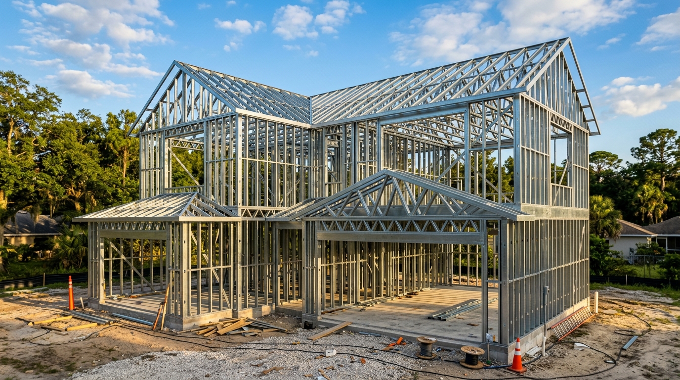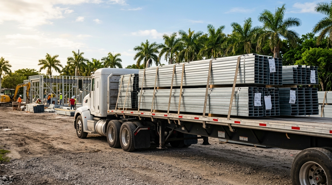
A framing package can be on site, installed quickly, and still create downstream problems if the metal stud framing details do not match the building’s structural, architectural, and MEP requirements. A missed deflection connection, an incorrectly reinforced opening, or a track that does not accommodate movement can turn a productive framing operation into costly rework. For commercial builders, details are not drafting formalities. They are the instructions that determine whether fabricated components fit, perform, and support the project schedule.
The most dependable framing systems begin with a coordinated approach to design intent, engineering, fabrication, and field installation. That approach reduces assumptions before material reaches the job site, where corrections are slower and more expensive.
Metal Stud Framing Details Start With System Intent
The first question is whether the assembly is non-load-bearing light-gauge framing, load-bearing cold-formed steel framing, or a structural infill system tied to a primary frame. Each application carries different requirements for stud depth, thickness, spacing, track configuration, fastening, bracing, and connection design.
A typical interior partition may use lighter studs sized primarily for wall height, finish loading, openings, and service penetrations. Exterior infill walls and structural assemblies often require a more detailed evaluation of wind pressure, axial load, drift, deflection, lateral bracing, and connection loads. Substituting a component based only on nominal depth can compromise the intended performance of the wall.
The drawings should clearly identify the framing designation, member size, steel thickness, coating requirements, spacing, and design criteria. Terms such as “metal studs at 16 inches on center” are not sufficient for an engineered assembly unless the detail also establishes the applicable stud series, gauge or mil thickness, loading condition, and connection requirements.
Confirm the Design Loads Before Fabrication
Structural framing details should trace back to the loads the assembly must resist. Depending on the project, that can include wind pressure, gravity load, out-of-plane loading, seismic movement, parapet forces, or loads transferred through headers and jambs. A wall that appears repetitive in plan may change significantly at corners, large openings, elevation transitions, or areas exposed to higher wind zones.
This is where precision-focused fabrication adds value. Components should be produced to the dimensions and profiles required by the approved framing design, not treated as interchangeable commodity pieces. Consistent member geometry helps installers maintain layout, connection alignment, and wall plane across long runs of framing.
Connections Must Accommodate Building Movement
One of the most consequential metal stud framing details is the connection at the top of wall. Structural slabs, beams, roof systems, and primary steel can deflect under live load, wind, or long-term building movement. If a partition or infill wall is hard-connected where movement must occur, the result may be bowed studs, cracked finishes, damaged joints, or unintended load transfer.
A slip track or deflection connection is commonly used where the wall needs vertical movement capacity while retaining lateral support. The required gap, slot length, clip configuration, fastener placement, and stud engagement all depend on the engineered detail. A generic slotted track does not automatically satisfy every deflection condition.
At the bottom of wall, tracks must be anchored at the required spacing and edge distance for the substrate. Connection selection also depends on whether the supporting surface is concrete, structural steel, wood blocking, or another approved condition. Fastener type and installation quality matter as much as spacing. An anchor that is improperly installed, overdriven, or placed too close to a slab edge may not deliver its published capacity.
Connections at columns, beams, expansion joints, and masonry interfaces deserve the same attention. These transitions often require clips, angles, slotted connections, or isolation details that preserve movement and maintain the wall’s intended line.
Openings Need More Than Header Depth
Door, storefront, glazing, louver, and equipment openings interrupt the normal stud pattern. Their framing must transfer loads around the opening while providing a stable attachment surface for the adjacent work. The header is only one part of the assembly.
Jamb studs, king studs, sill members, cripples, clip angles, and fastening requirements should all be identified where applicable. A large opening can introduce concentrated loads and higher connection demands that are not addressed by simply doubling standard studs. Reinforced jambs may need heavier members, boxed configurations, tube steel, or engineered assemblies based on opening width, wall height, and applied loads.
Coordination is especially important at rated doors and specialty frames. Frame manufacturers may require specific stud thicknesses, jamb reinforcement, anchorage patterns, or clearance conditions. Those requirements need to be resolved before fabrication and installation, not after the frame arrives on site.
Tolerances Protect Layout and Finish Quality
Commercial framing must accommodate real-world variation in concrete, structural steel, and adjacent trades. The goal is not to assume every substrate is perfectly located. The goal is to establish tolerances and details that allow the framing system to be installed plumb, aligned, and within the requirements of the finishes it supports.
Track layout should be verified against control lines, opening locations, embeds, slab edges, and MEP penetrations. Where existing conditions vary, field verification may be necessary before releasing fabricated material. Long runs of wall, corridor alignments, shaft walls, and exterior planes are particularly sensitive to small dimensional errors that accumulate across the building.
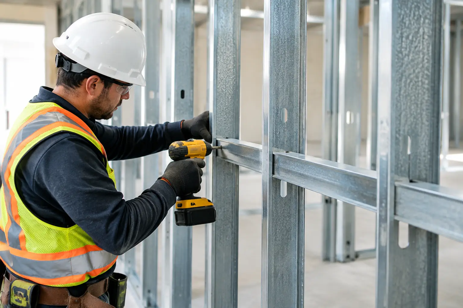
Studs must also be installed plumb and properly seated within track. Overcut or undercut studs, inconsistent track widths, and damaged flanges can slow installation and create uneven wall surfaces. Quality-controlled manufacturing supports a cleaner fit, but field crews still need an installation process that protects member condition and follows the approved details.
Coordinate Fire, Acoustics, and MEP Before the Wall Closes
Metal framing often supports several building-performance requirements at once. A partition may need a fire-resistance rating, acoustic performance, impact resistance, insulation, backing, and clearance for mechanical or electrical systems. The framing detail must make room for all of them.
For rated assemblies, component substitutions can be consequential. Stud size, spacing, track configuration, shaftwall components, gypsum board layers, fastener patterns, and joint treatments may all be part of the tested or listed assembly. A field adjustment that seems minor can affect compliance if it falls outside the governing system requirements.
Acoustical partitions require similar discipline. Unintended bridging at tracks, penetrations, or resilient details can reduce the performance expected from the wall. Details should identify where sealant, isolation, insulation, or specialty clips are required, then coordinate those requirements with the installation sequence.
MEP coordination should address penetrations, support loads, access panels, and equipment backing. Stud web punchouts are useful only within the member manufacturer’s limits and the engineered design. Cutting large holes, removing flanges, or placing unsupported loads on light-gauge framing without an approved detail can weaken the assembly and complicate inspection.
Use Submittals to Resolve Details Before Procurement
The submittal stage is the practical checkpoint between design intent and field execution. It should confirm that the proposed light-gauge or structural framing system matches the contract documents, engineering requirements, and project-specific conditions.
A complete review typically considers member properties, connection details, shop or panel drawings where required, coatings, accessories, opening reinforcement, deflection provisions, and compatibility with rated assemblies. It should also identify details that require field measurement or coordination with steel, concrete, glazing, drywall, and MEP trades.
This process is not meant to create paperwork for its own sake. It gives the project team an opportunity to identify conflicts while adjustments are still controlled. Once framing is underway, a missing detail can affect multiple trades and turn a local issue into a schedule event.
Fabrication Consistency Is a Field Productivity Issue
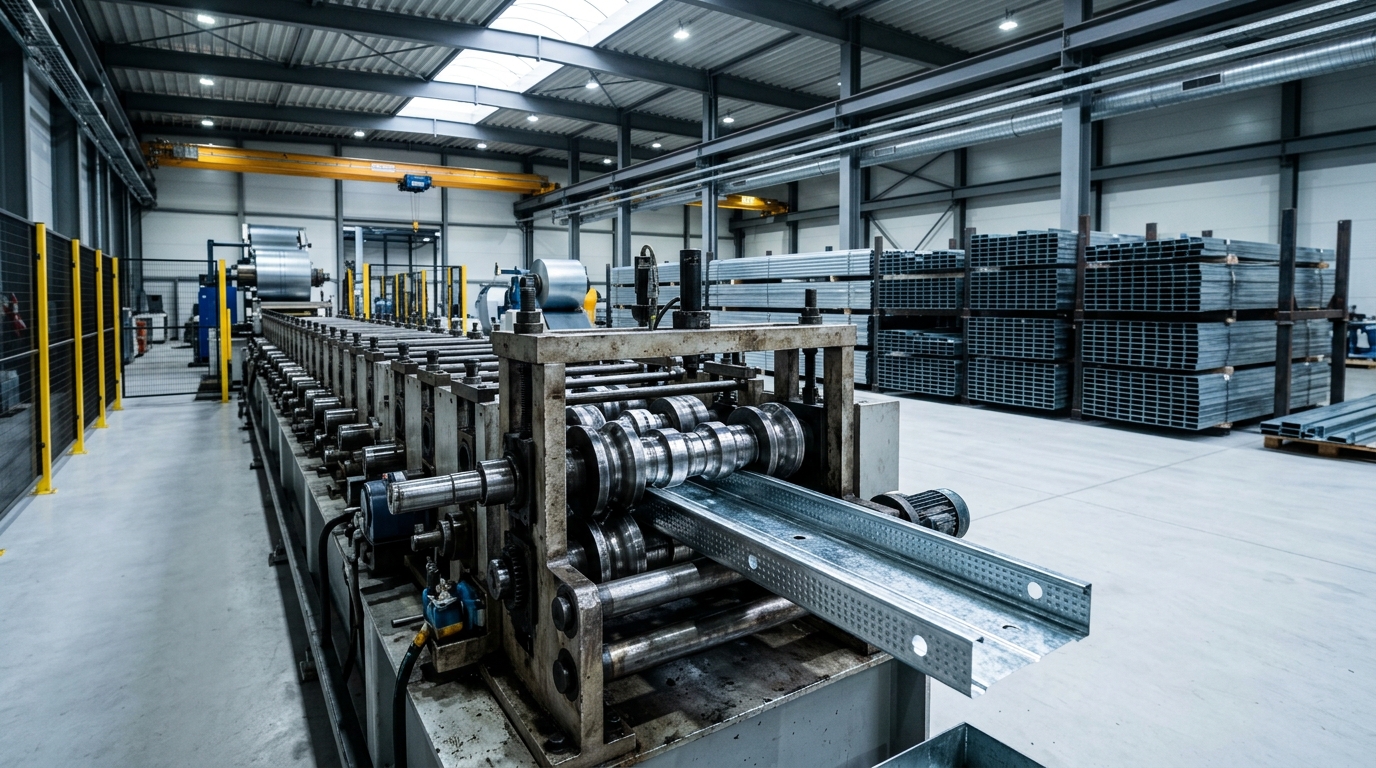
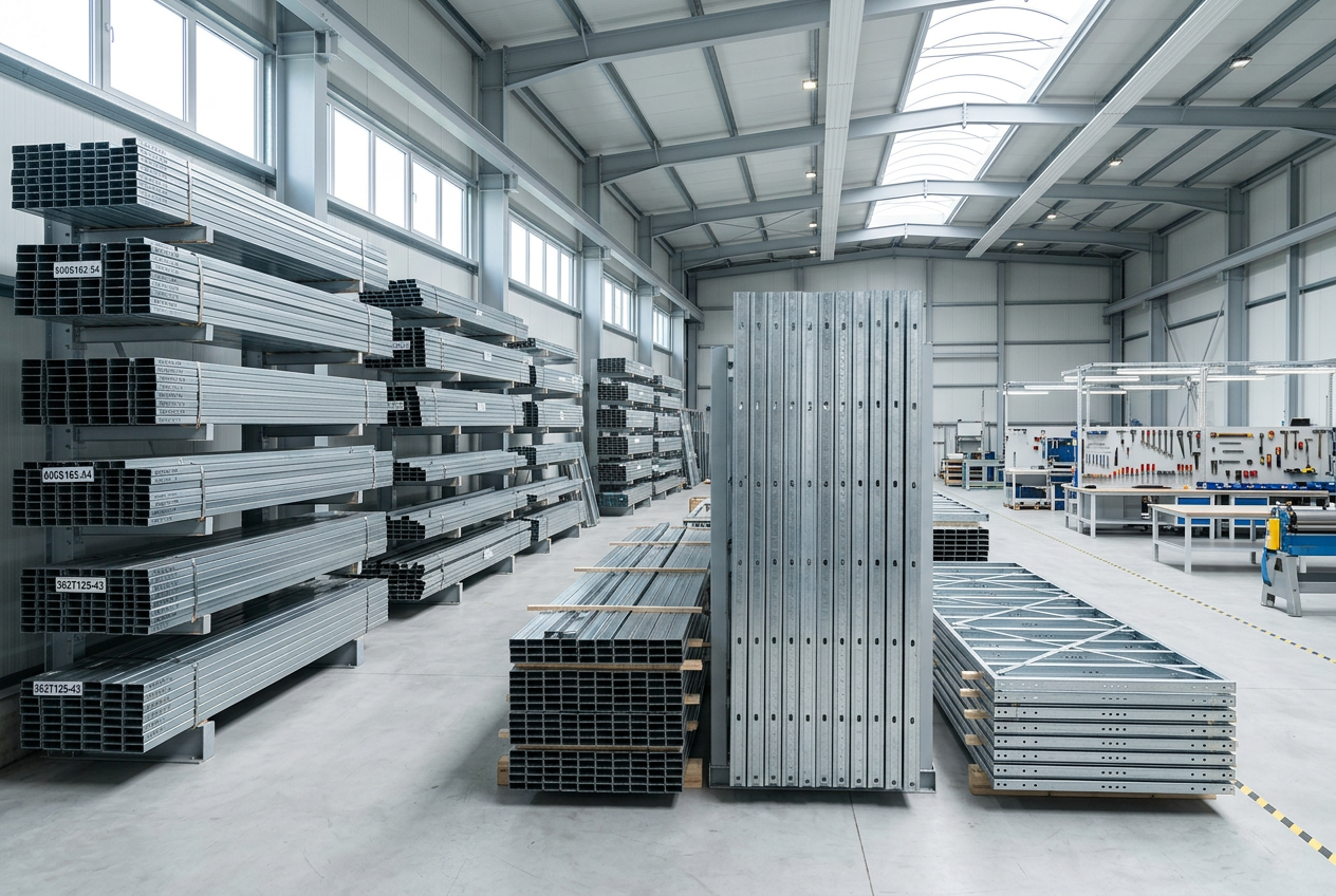
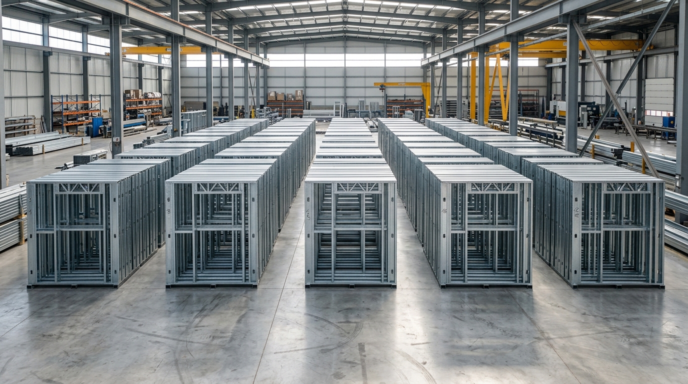
Accurate metal framing components improve more than appearance. Consistent lengths, profiles, and cut quality help crews maintain production rates, reduce sorting and modification, and install framing according to the approved layout. On commercial work, that consistency becomes more valuable as wall counts, opening counts, and project scale increase.
VRD Metal Framing approaches fabricated framing as a quality-controlled construction input. For builders and framing contractors, the objective is straightforward: receive specification-aligned components that support accurate installation rather than introduce avoidable field decisions.
The best framing detail is one the field can execute without improvisation. When engineering, fabrication, and installation are aligned early, the wall system has a better chance of staying straight, performing as designed, and keeping the work moving when every trade behind it is ready to proceed.