Deflection track is a small component with a major role in commercial wall performance. A disciplined deflection track installation guide helps framing crews maintain the separation required between non-load-bearing partitions and a structure that may move under live load, creep, thermal change, or roof and floor deflection. When the track is installed as a fixed head condition, the wall can receive structural movement it was never designed to carry.
For commercial builders, the objective is not simply to install a slotted track at the top of a wall. The objective is to execute the engineered head-of-wall detail accurately, preserve the intended movement allowance, and coordinate the assembly with firestopping, acoustical requirements, door frames, MEP penetrations, and finishes. Precision begins before the first fastener is driven.
Confirm the Deflection Track Detail Before Layout
Deflection track should be installed only from the approved project documents, structural drawings, architectural wall types, and the manufacturer’s tested or engineered assembly details. Terms such as slip track, slotted track, deep-leg track, and deflection track are often used on site, but they do not automatically describe the same product or movement capacity.
Review the specific wall condition. Confirm whether the partition is non-load-bearing, what movement is anticipated, the required track leg depth, stud size and gauge, fastener type, and whether the wall must meet a fire-resistance or sound-transmission rating. A corridor wall with a listed head-of-wall joint may have requirements that differ substantially from an interior office partition, even when both use similar studs.
The specified clearance is particularly critical. Some details require a gap between the stud and the track web or upper track leg so the structure can move independently. Others use a proprietary connection or clip system. Do not estimate this distance based on a prior project or substitute a similar-looking track without confirming equivalency.
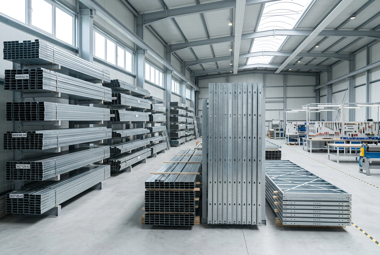
Before material reaches the work area, inspect the track for straightness, correct leg configuration, slot pattern, flange condition, coating condition, and fabrication consistency. A bent leg, damaged slot, or inconsistent profile can slow installation and make correct stud engagement difficult. Quality-controlled framing components reduce field correction and support more predictable layout.
Deflection Track Installation Guide: Layout and Fastening
Accurate layout protects the wall line, opening locations, and alignment of connected assemblies. Establish the partition line from approved control lines, then transfer it to the structural deck or supporting member above. Check that the wall location aligns with floor penetrations, ceiling transitions, door frame locations, and overhead obstructions before fastening the track.
Where required, install approved isolation tape, sealant, or gasket material at the track interface. This may support acoustical, smoke, air, or firestopping performance, but the selected material must match the tested assembly or project specification. Generic sealant is not a substitute for a listed joint system.
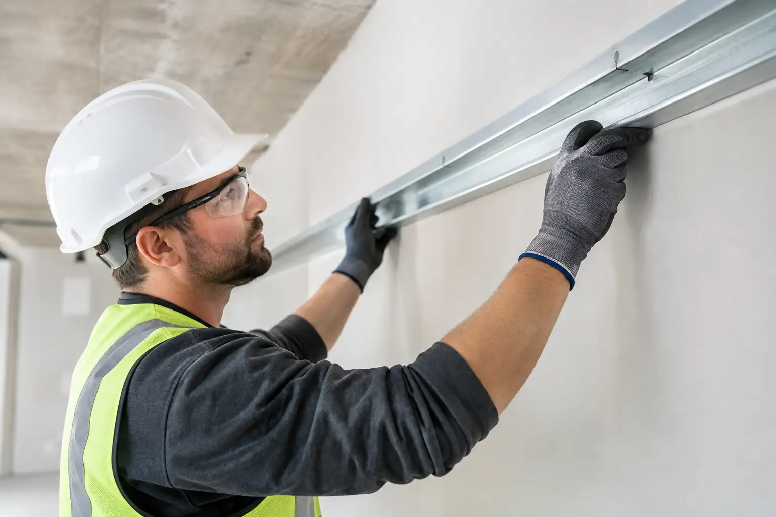
Fasten the deflection track to the structure using the fastener type, spacing, and edge distances identified by the design documents and track manufacturer. Fasteners must engage suitable structural backing. Attachment into a deck type that lacks the required capacity, or into unsupported flutes without an approved detail, can compromise the connection and create inspection issues.
Maintain the track straight and continuous along the wall line. If splices are necessary, use the manufacturer’s method or the approved project detail. Avoid creating a rigid bridge across a movement joint through overlapping material, excessive fastening, or an unapproved connector. The track must remain securely attached to the structure while allowing the stud-to-track relationship to perform as designed.
At building expansion joints, seismic joints, and transitions between structural systems, stop and verify the detail. A standard deflection track does not automatically accommodate every movement condition. These locations often require specialized joint assemblies, independent wall segments, or tested firestopping systems.
Set Studs Without Restricting Movement
The defining installation requirement is simple: studs must be retained laterally without being locked into a vertical load path when the wall is designed as non-load-bearing. The exact connection method depends on the track design.
With slotted deflection track, fasteners are commonly placed through the slots in a manner that permits vertical movement. The fastener location, washer requirement, screw type, and tightening condition matter. An overdriven screw can clamp the stud connection and defeat the purpose of the slot. A fastener installed at the wrong position within the slot can reduce available movement or create interference during structural deflection.
With deep-leg track, studs may be left unattached at the top or connected with an approved clip or screw detail that maintains the specified clearance. The studs must be cut to the correct length. Studs cut too long can bind against the track web or upper leg. Studs cut too short can lose lateral support, affect wall-plane alignment, and complicate drywall installation.
Plumb each stud before final attachment at the bottom track and at any approved intermediate bracing. Maintain the scheduled stud spacing and place reinforcing members where required for door frames, wall-mounted equipment, backing, grab bars, cabinets, and mechanical supports. A deflection head condition does not eliminate the need for a complete framing system below it.
Do not field-weld studs to deflection track unless specifically designed and approved. Welding can damage protective coatings, introduce distortion, and create an unintended rigid connection. Likewise, avoid packing the head condition with scrap steel, shims, insulation, or drywall fragments that limit the designed movement space.
Coordinate Firestopping, Acoustics, and Finishes
Head-of-wall joints are commonly part of rated and acoustically sensitive assemblies. The framing installation must leave the correct joint geometry for the firestop contractor or framing crew to install the specified system. If the deflection gap is reduced, overfilled, or bridged with rigid material, the tested joint design may no longer apply.
Coordinate early with firestopping requirements. Confirm the nominal joint width, movement capability, backing material, mineral wool depth, sealant type, and any required compression. The firestop system must accommodate movement without breaking adhesion or creating a path for smoke and flame. This is an assembly issue, not a separate trade issue.
Acoustical walls deserve the same attention. A wall can include insulation and multiple layers of gypsum board yet underperform if the head condition is improperly sealed or if framing components create unintended flanking paths. Follow the architectural acoustical detail for sealant placement, track isolation, and gypsum board termination.
Drywall installation must also respect the head-of-wall condition. Gypsum board should terminate as required by the tested or specified assembly, not be forced tightly against a moving deck or fastened in a way that transfers structural movement into the wall finish. Cracked board at the ceiling line is often a visible sign that the movement detail was misunderstood or bypassed.
Inspect the Work Before It Is Concealed
Deflection track errors are easiest to correct before gypsum board, firestopping, and ceiling components conceal the wall. A focused pre-close inspection should verify the following conditions:
- Track profile, gauge, leg depth, and movement capacity match the approved detail.
- Track is aligned, continuously supported, and fastened to approved structural backing.
- Stud lengths preserve the required clearance and do not bear on the track where movement is required.
- Slotted connections use the specified fasteners and have not been over-tightened.
- Door openings, wall intersections, backing, and bracing are installed without creating a rigid head connection.
- Firestop and acoustical joint dimensions remain available for the specified assembly.
Document discrepancies promptly. Common field corrections include replacing overdriven fasteners, recutting long studs, revising a track splice, or removing material that bridges the deflection gap. These corrections are typically straightforward before finishes begin and far more disruptive after the wall is closed.
Common Installation Failures and Their Cost
The most frequent failure is treating deflection track like standard top track. A crew may fasten every stud tightly, omit the required gap, or use screws that do not permit slot movement. The wall may look acceptable at turnover, but structural movement can later produce cracked gypsum board, separated sealant, damaged finishes, and costly corrective work.
Another common issue is poor coordination at doors and soffits. Heavy-gauge jamb framing, drywall bulkheads, and ceiling support members can accidentally tie a non-load-bearing wall to the structure. Each condition should be reviewed as a load path question: does this connection allow the building structure to move without imposing that movement on the partition?
Material consistency also affects installation quality. Track dimensions that vary, slots that are poorly formed, or components that arrive damaged create field improvisation. For commercial projects, precision-focused fabrication and incoming quality control support faster installation, cleaner inspection outcomes, and fewer corrective actions.
A correctly installed deflection track is not merely a framing detail above the ceiling. It is a controlled interface between moving structure and finished partition. When the track, studs, fasteners, firestopping, and finishes are coordinated from the approved detail, the wall is positioned to perform as intended long after the job is complete.